STEP 01
Materials & components
Check the selected profiles, glass or panels, gaskets and hardware against the approved configuration.

Configuration & application references. Final details follow the approved order.
WS-CW-014
Made-to-order Structural Glass Facade. Share your opening sizes, application and destination for a configuration proposal.
Explore the materials, construction, configuration choices, manufacturing steps and packing for this product series.
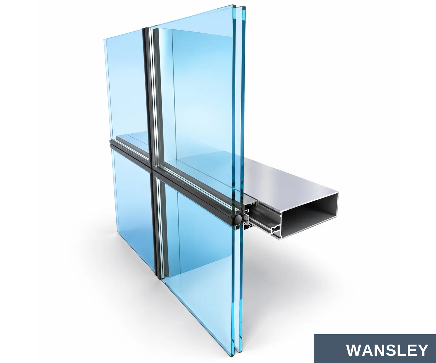
Understand the interfaces behind the glass face.
INSULATING GLASS
ALUMINIUM SECTION
SEALS & SUPPORT
Glass lites and sealed cavities form the specified unit.
The hollow profile supports the glazing system.
Gaskets, blocks, spacers and retention details act together.
Review the complete section.
Confirm profile depth, glazing pocket, edge support, drainage and connection details with the approved system. This image explains a section concept.
Coordinate structural sections with a consistent facade palette.
Dark grey Black White Bronze tone Silver tone
PROFILE SELECTION
FINISH SELECTION
Specify alloy and temper, wall thickness, section depth and connection details for the chosen system. These are confirmed with the drawings and project requirements.
Review powder coating, anodizing or other specified finishes with the required exposure conditions. Approve the color and texture against a physical sample.
Color swatches are indicative; available finishes depend on the selected product.
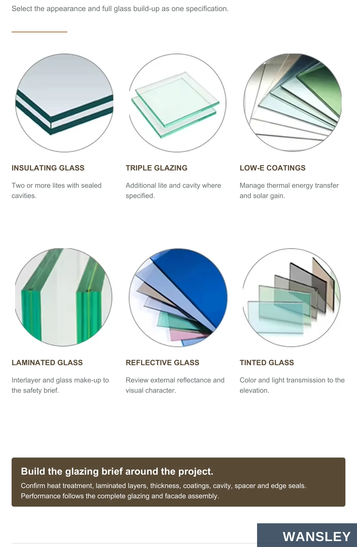
Select the appearance and full glass build-up as one specification.
INSULATING GLASS
TRIPLE GLAZING
LOW-E COATINGS
Two or more lites with sealed cavities.
Additional lite and cavity where specified.
Manage thermal energy transfer and solar gain.
LAMINATED GLASS
REFLECTIVE GLASS
TINTED GLASS
Interlayer and glass make-up to the safety brief.
Review external reflectance and visual character.
Color and light transmission to the elevation.
Build the glazing brief around the project.
Confirm heat treatment, laminated layers, thickness, coatings, cavity, spacer and edge seals. Performance follows the complete glazing and facade assembly.
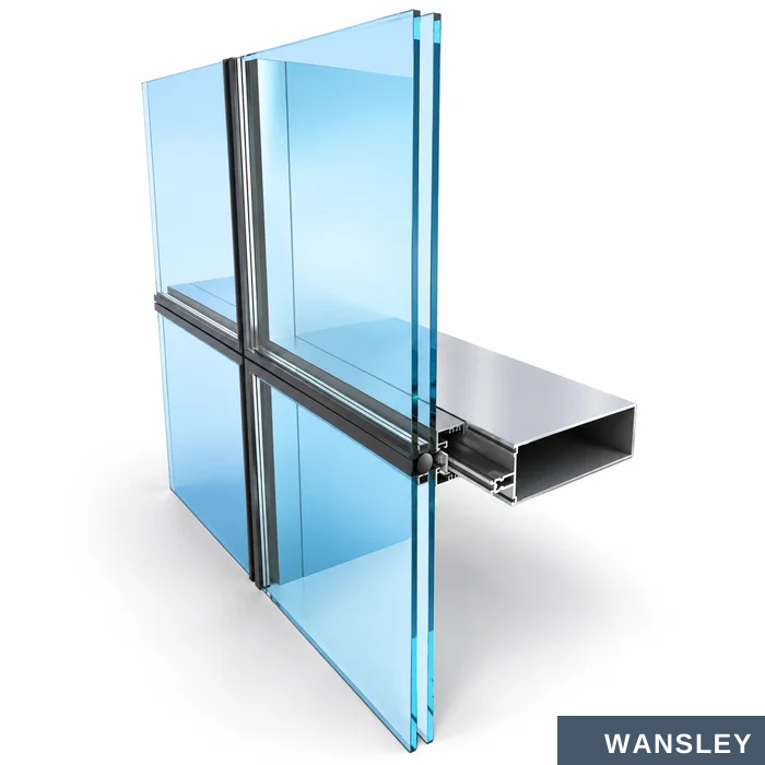
Performance comes from the complete facade assembly.
AIR & WEATHER SEALS
DRAINAGE PATHS
Coordinate internal and external seals, perimeter junctions and compatible materials.
Keep intended drainage and pressure-equalization paths continuous through the specified joints.
THERMAL STRATEGY
MOVEMENT & VERIFICATION
Review thermal breaks, insulated glazing, spandrels and perimeter interfaces together.
Allow for the designed building and thermal movement. Agree required calculations and project testing.
No universal air, water, wind, thermal or acoustic rating is implied by an image.
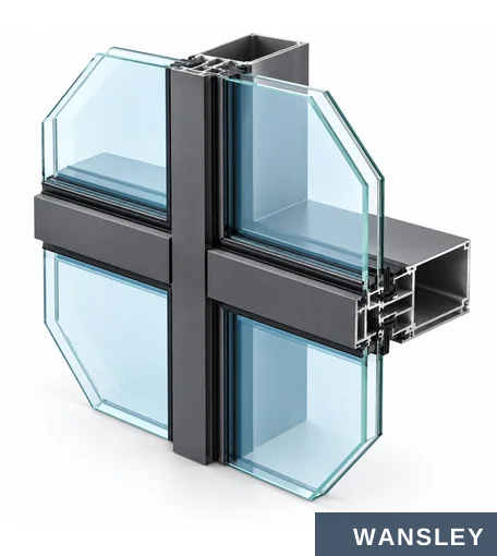
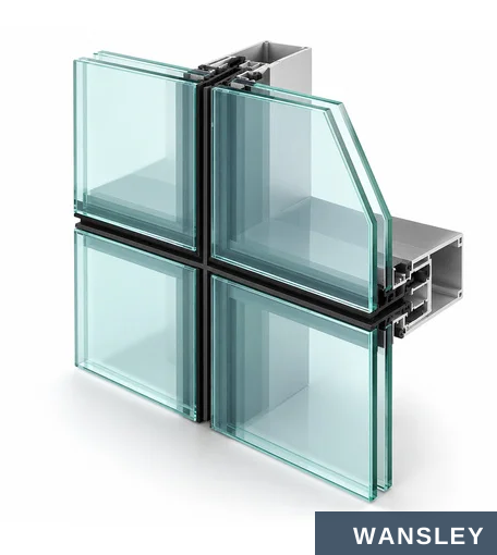
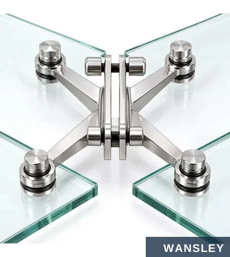
Appearance and fabrication method are separate project decisions.
CAPTURED / FRAMED
STRUCTURALLY GLAZED
POINT-SUPPORTED
Visible pressure plates and cover caps define the glazed grid.
A flush glass face with silicone joints and support behind.
Engineered fittings connect the glass to its supporting structure.
MATCH THE COMPLETE SYSTEM
Review the intended external look together with glass support, profile sections, seals, anchors and installation access. The pictured details explain different concepts; components from different systems are not automatically interchangeable.
Section and fixing images are conceptual product illustrations.
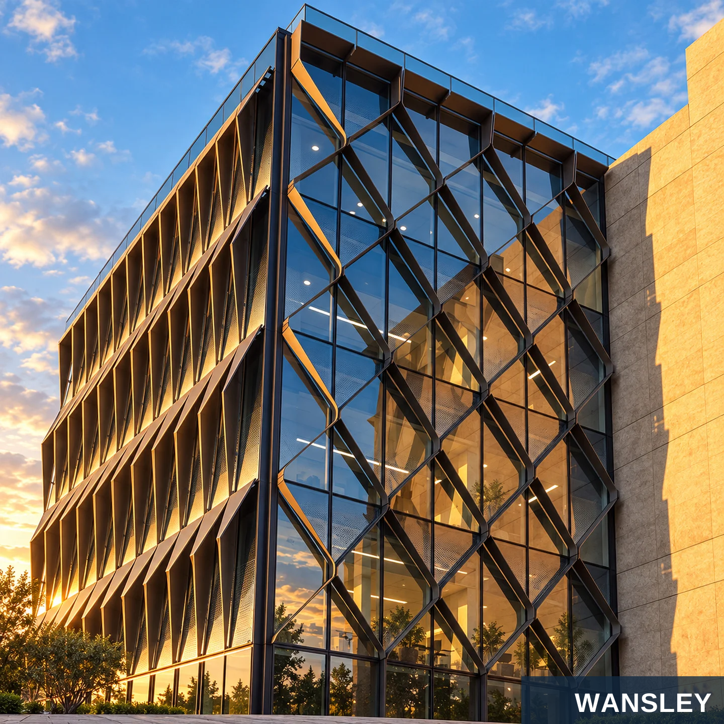
Architectural glazing for distinctive building envelopes.
A clear expression of your architecture.
Coordinate the glass appearance, aluminium framing, joints and installation approach around the building design. From clean framed grids to flush glass faces, each facade begins with a considered project brief.
FACADE DESIGN
SYSTEM CHOICE
MATERIAL BRIEF
PROJECT SUPPLY
Grid, glass and sightlines
Framed or flush expression
Profiles, glazing and seals
Drawings through delivery
Architectural images illustrate design possibilities.

A non-load-bearing external envelope formed around the building structure.
Curtain walls combine glass or infill panels with a supporting frame or engineered fixing system. The facade is attached to the primary building structure and brings the glazing layout, perimeter interfaces and weathering details together.
GLASS & INFILL
FRAME & FIXINGS
BUILDING INTERFACES
Select visibility, reflectance,
Coordinate mullions, transoms,
privacy and opaque zones.
brackets and joints.
Resolve slab edges, corners,
perimeter seals and movement.
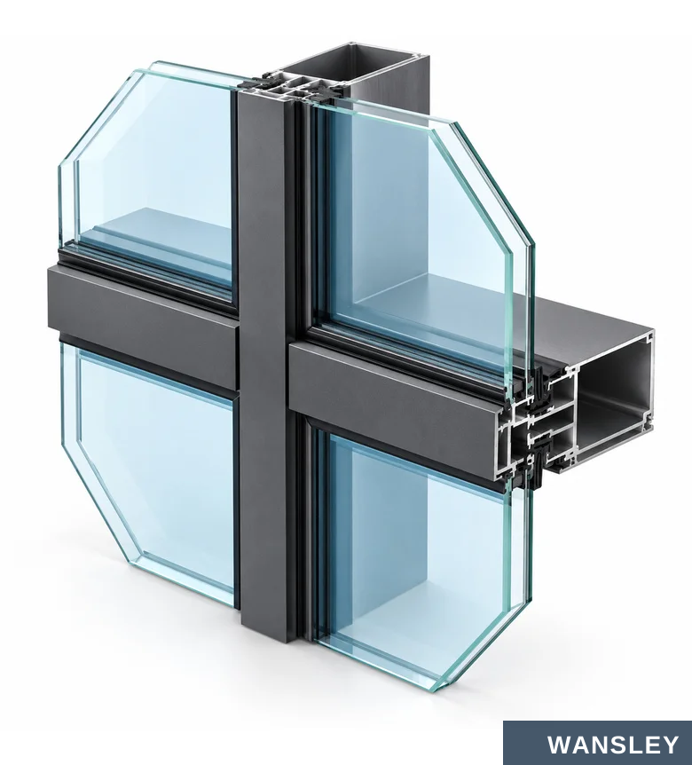

Pressure plates and cover caps create a clear architectural grid.
MULLIONS & TRANSOMS
Vertical and horizontal members form the
glazed framework.
PRESSURE PLATES
Mechanical glazing retention follows the
selected system.
COVER CAPS & GASKETS
Caps shape the external look; compatible
gaskets seal glazing interfaces.
FRAME RHYTHM, MATERIAL AND PROPORTION
Coordinate cap shape, frame color, glass appearance and bay dimensions with the facade elevation. Profile depth and fixing details are selected for the project.
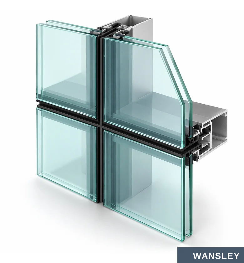

Flush glass faces with carefully designed joints and concealed support.
CONTINUOUS GLASS EXPRESSION
A structurally glazed arrangement can reduce the appearance of exterior framing. Two-sided or four-sided layouts follow the selected system.
JOINTS & COMPATIBILITY
Structural silicone, substrate preparation, glazing support and curing controls are specified as one coordinated assembly.
STRUCTURAL BONDING AND WEATHER SEALING
These are distinct functions. Confirm the adhesive, weatherseal, substrates, joint geometry and quality records for the project. A weatherseal is not automatically a structural glazing adhesive.
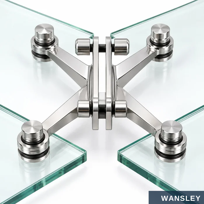
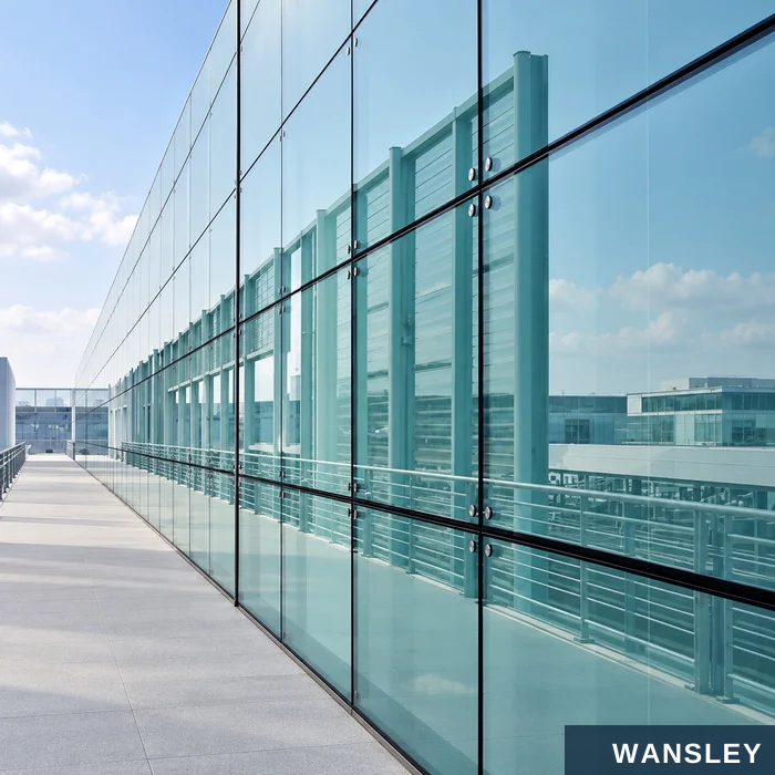
Discrete fittings and transparent glass surfaces.
GLASS FIXINGS
SUPPORT STRUCTURE
Articulated fittings and compatible bearing details connect specified glass panels.
Glass fins, steel members or other engineered supports carry the glazing loads.
PANEL & JOINT DESIGN
APPLICATION PLANNING
Glass type, holes, edge distances and joint movement follow the engineered design.
Review entrance areas, atria and other facade locations with access and maintenance needs.
Choose fittings, glass build-up and supporting structure together. The connector image is illustrative and does
not define a load capacity or a fixing schedule.
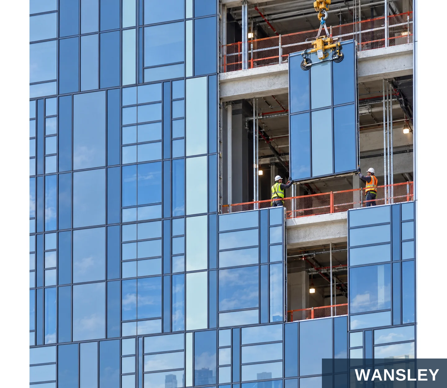
Two approaches to organizing fabrication and installation.
STICK CONSTRUCTION
UNITIZED CONSTRUCTION
Mullions and transoms are assembled into the facade grid, with glazing and sealing completed through the agreed site sequence. Site access and weather conditions influence planning.
Frames and glazing are assembled into modules in the workshop. Modules are transported to site and connected through the specified anchors and interlocking joints.
Select the approach for building geometry, repetition, logistics and installation strategy. The external glazing
expression can vary within either construction family.
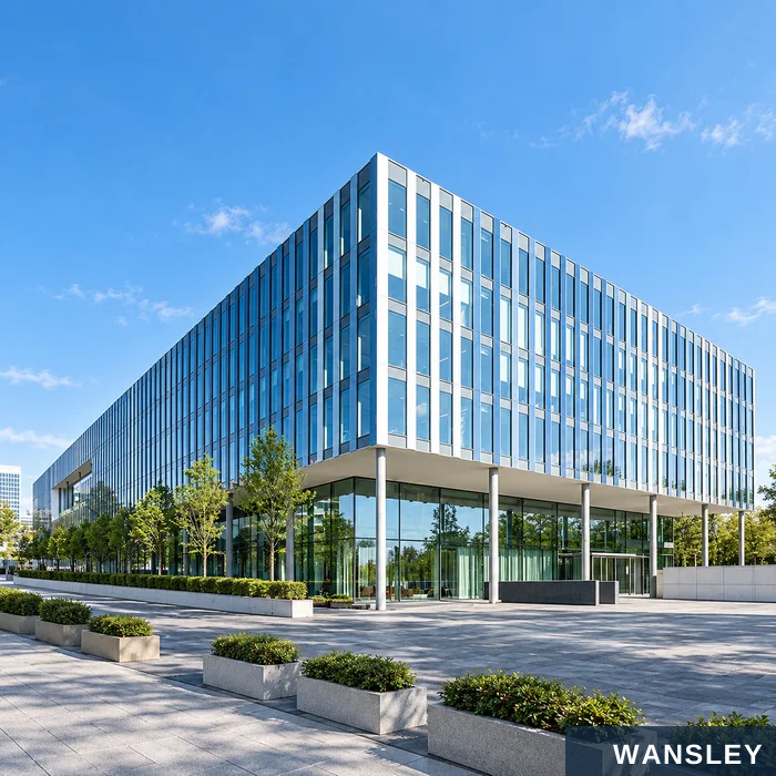
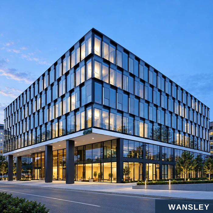
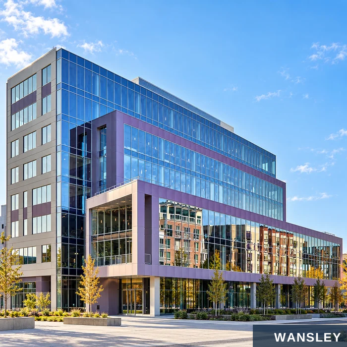
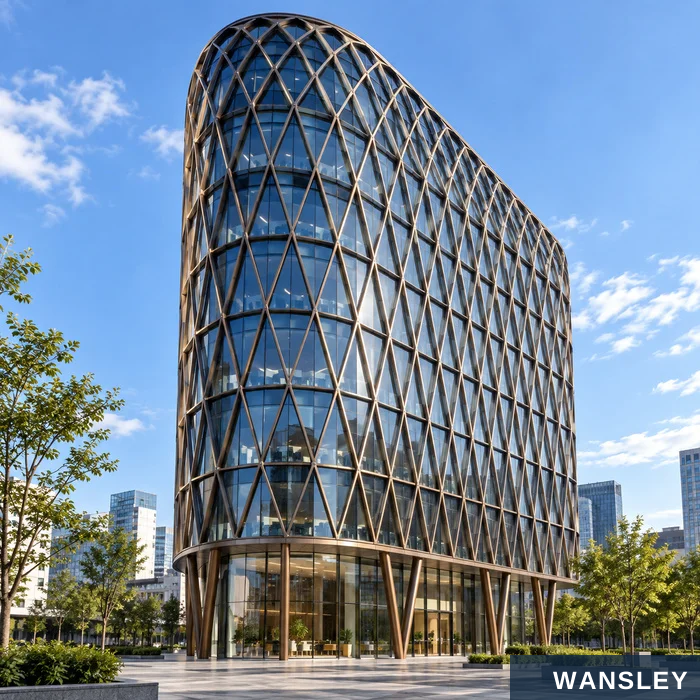
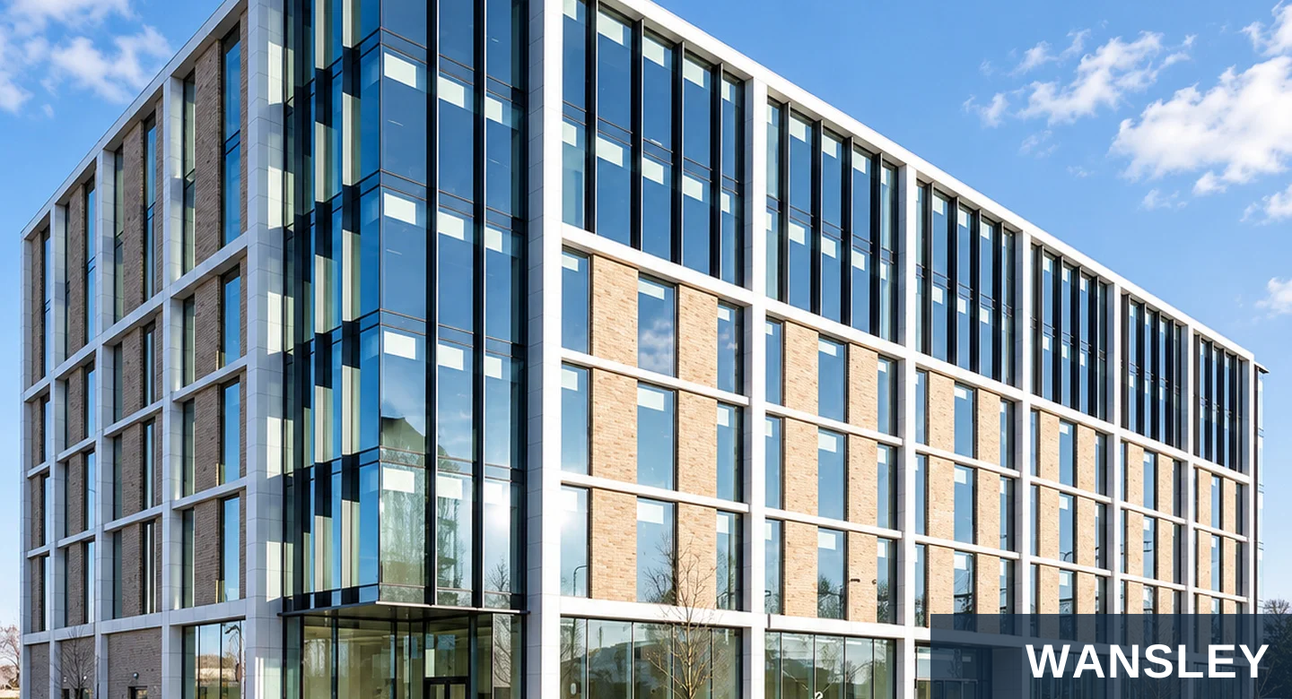
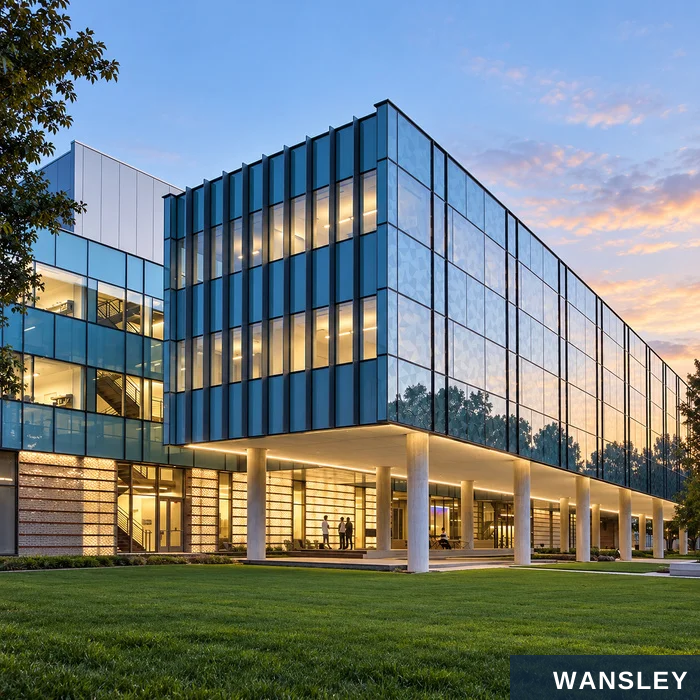
Repeated grids, vertical fins and diagonal architectural expressions.
Vertical fins / campus facade Dark-framed / modular office
Stepped volumes / glazed facade Diagrid / office tower
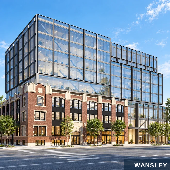


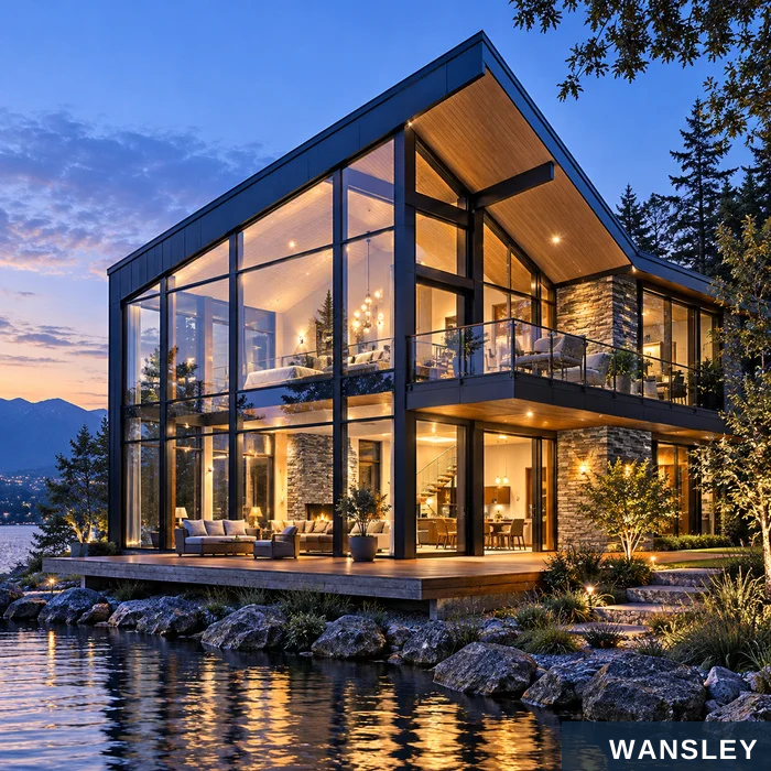
Examples for offices, public buildings and residential architecture.
Glass extension / brick facade Public building / glazed corner
Office / curved glass corner Residential / glazed gable

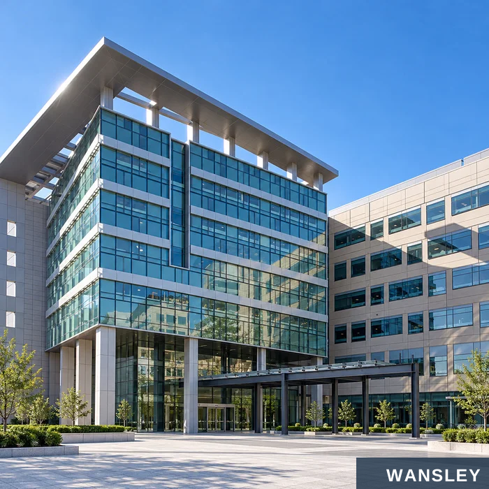
Connect the glazing with entrances, corners, infill and shading.
ENTRANCES & OPENING ELEMENTS
VISION & SPANDREL ZONES
Separate transparent areas from opaque infill and resolve the slab-edge interfaces.
Coordinate compatible doors, vents and access requirements within the elevation.
CORNERS & TRANSITIONS
SHADING & ACCESSORIES
Review internal or external corners, returns and connections to other wall materials.
Coordinate fins, canopies and attachments with their support and drainage details.
A coordinated facade detail connects the visible design with the supporting structure, weathering strategy and installation sequence.
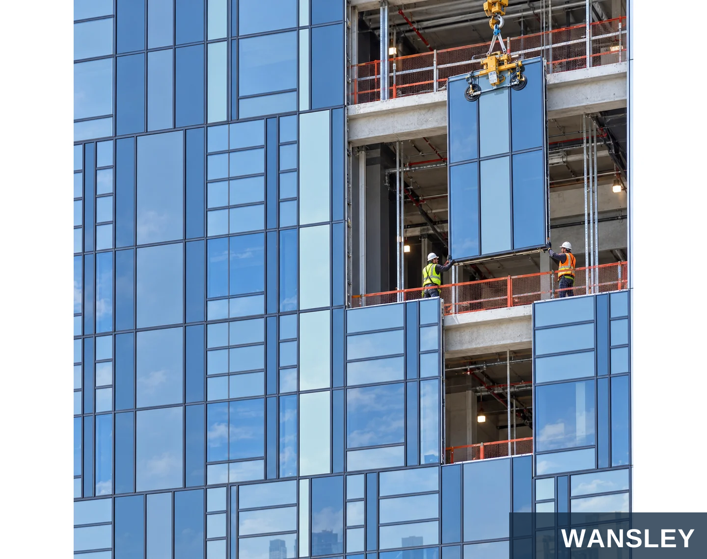
Turn the approved facade design into an organized site sequence.
SITE & SETTING OUT
ANCHORS & SUPPORT
Review survey information, slab edges, tolerances and
Confirm fixing locations, adjustment allowances and
the approved grid.
interfaces with the structure.
FRAME OR MODULE PLACEMENT
JOINTS & COMPLETION
Plan handling, access and installation in the approved
Complete system joints, perimeter seals, protection
sequence.
and agreed inspections.
Installation scene is illustrative; the project method and engineered details govern the works.
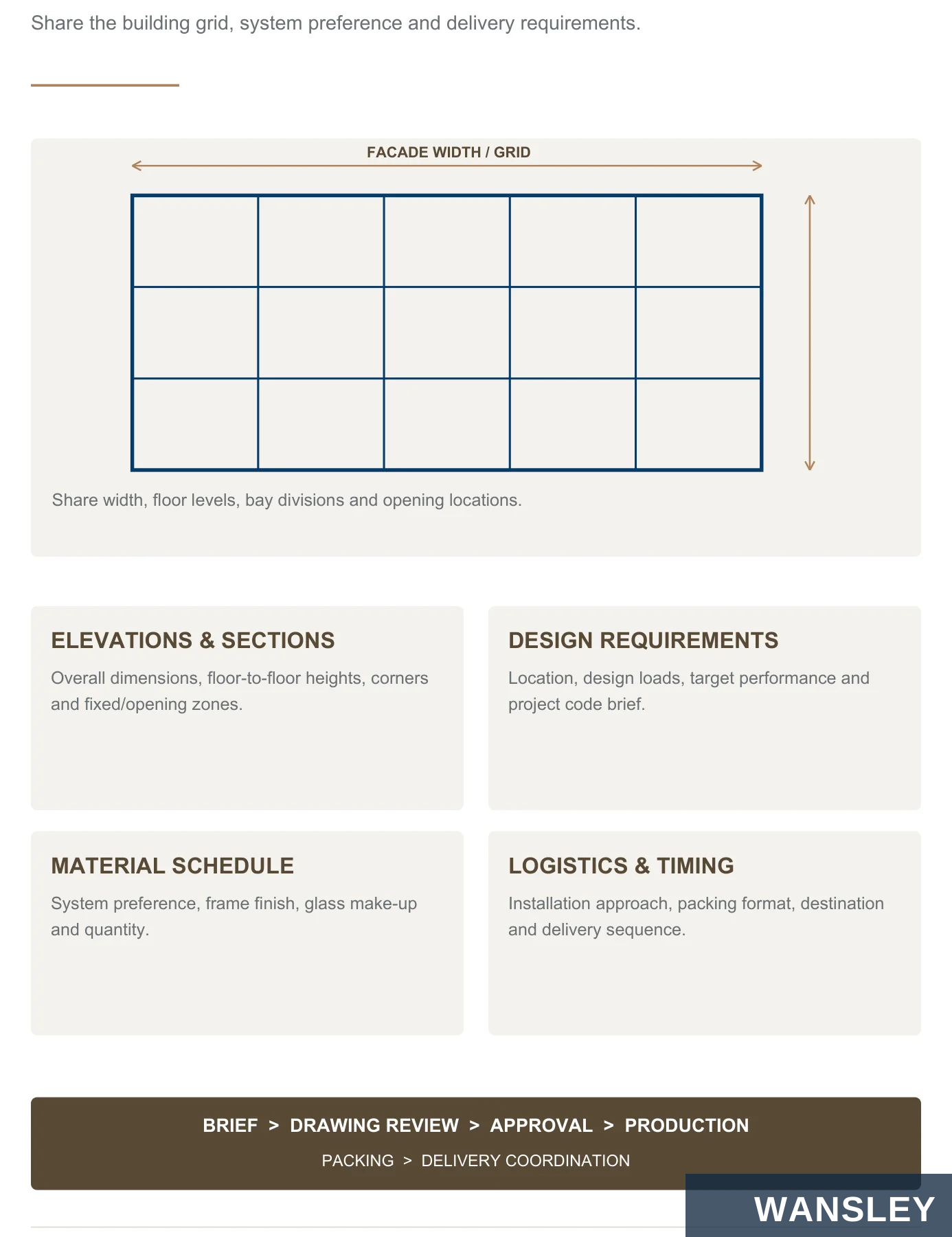
Share the building grid, system preference and delivery requirements.
FACADE WIDTH / GRID
Share width, floor levels, bay divisions and opening locations.
ELEVATIONS & SECTIONS
DESIGN REQUIREMENTS
Overall dimensions, floor-to-floor heights, corners and fixed/opening zones.
Location, design loads, target performance and project code brief.
MATERIAL SCHEDULE
LOGISTICS & TIMING
System preference, frame finish, glass make-up and quantity.
Installation approach, packing format, destination and delivery sequence.
BRIEF > DRAWING REVIEW > APPROVAL > PRODUCTION
PACKING > DELIVERY COORDINATION


Prepare the aluminium sections for the selected curtain wall system.
01 CUTTING & MACHINING
Cut the specified profiles and machine the connector, anchor and drainage features shown in the fabrication documents. Keep frame references linked to the approved elevation.
02 FRAME ASSEMBLY
Fit the system connectors, fasteners, seals and support components. Review alignment, corner joints and frame dimensions before the next fabrication stage.
Production scenes are illustrative; equipment and operations vary by system.


Complete the specified assembly and review the finished components.
03 GLAZING & SEALING
Position the glass with the specified supports and retention details. For structurally glazed units, control substrate preparation, sealant application and curing as specified for the project.
04 DIMENSIONS, JOINTS & FINISH
Review frame dimensions, glass seating, seals, joints and visible surfaces against the approved schedule. Record unit references and agreed checks before protection and packing.
Production and inspection scenes are illustrative.
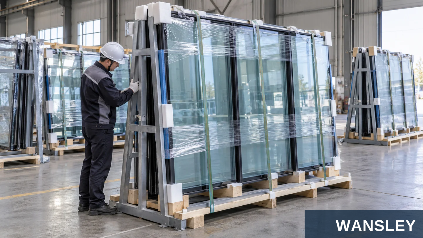
Protect the facade components through handling and transport.
SUPPORT & SEPARATION
SURFACE & EDGE PROTECTION
Use the agreed stillage, crate or other packing arrangement with suitable padded contact points.
Protect glass edges, frame corners and visible finishes from contact damage.
UNIT ORGANIZATION
SITE DELIVERY
Link packed units and loose accessories to the project schedule and shipment list.
Confirm transport, unloading access, storage and installation sequence with the project team.
Packing scene is illustrative; the final shipment format is agreed with the order.
Confirm the system, materials and project scope before quoting.
Which curtain wall styles can be reviewed?
How do stick and unitized systems differ?
The collection illustrates captured aluminium
Stick systems organize framing and glazing through
framing, structural silicone glazed faces and
the site assembly sequence. Unitized systems use
point-supported glass concepts. Confirm the
workshop-assembled glazed modules connected on
appropriate system for the project.
site.
Can the grid and frame finish be customized?
Which glass options are available to discuss?
Share elevations and the intended appearance. Bay
Review insulating, Low-E, laminated, tinted,
sizes, section selection, cap profiles and finishes
reflective and privacy glazing. Confirm the complete
follow the chosen system and approved drawings.
build-up, thickness and required heat treatment.
How are performance requirements handled?
Can doors, vents and shading be coordinated?
Provide the project location, design loads and target
Discuss compatible opening elements, entrance
air, water, wind, thermal and acoustic requirements.
interfaces, spandrels, corners and shading supports
Assessment follows the complete selected
with the facade drawings.
assembly.
What information is needed for packing?
How do we start an inquiry?
Send elevations, sections, dimensions and
reference images. Add glass and frame
Share unit dimensions, quantities, delivery order,
destination and unloading conditions so the packing
preferences, performance brief, quantity and
and handling format can be agreed.
required delivery timing.
Materials, dimensions, finish and operating parts are coordinated with the approved drawing for the selected system.
Check the selected profiles, glass or panels, gaskets and hardware against the approved configuration.

Prepare component lengths, fixing positions, drainage and hardware interfaces for the selected system.

Assemble the frame, sash or panels with the specified connectors and operating hardware.

Fit handles, locks, hinges, tracks or drive components and check their operation.

Fit the specified glazing or infill, seals and finishing components.

Check dimensions, finish, movement and identification; protect surfaces, corners and loose accessories for shipment.
Workshop images illustrate the supplied production environments. Equipment and the sequence of operations depend on the selected product.

WANSLEY is a professional Chinese manufacturer of architectural windows and doors, with more than a decade of production and export supply experience. We bring research and development, manufacturing and sales together to deliver one-stop solutions for the whole building.
Share your opening schedule, destination, preferred material, finish and operating requirements. Our team will coordinate system selection, drawings, manufacturing, inspection and export preparation.
This series guide presents configuration and application references. Individual illustrations can show alternative systems or finishes. Material, construction, dimensions, operating hardware, performance documentation and packing follow the final approved product specification.
WS-CW-014
Send your dimensions, quantity, destination and preferred finish. Our team will help confirm the next steps.